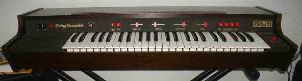
The Eminent Solina is a famous string synthesizer from the 70’s.
It is based on a paraphonic oscillator, a simple envelope and a phaser.
The oscillators in the original was a divide down structure where you generate the frequencies for the top octave and divide those down by modulo 2 for the rest of the octaves.
We can’t really use a signal for every key so we use an alogorithm for generating 8 Saw waves and distribute those among the keys played on the keyboard.
Paraphonic means it’s kind of polyphonic but shares some parts of the soundpath.
In this case it’s the envelope shared by all the keys played on the keyboard.
So what does it sound like?
(From http://bloghoskins.blogspot.com/2016/11/diy-arduino-string-synth.html)
Pretty nice eh?
So what do we need to build our string synth?
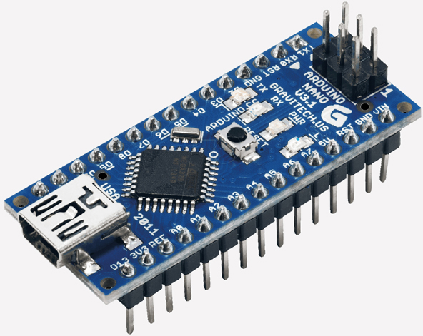
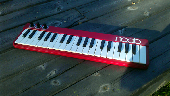
An Arduino Nano, 3 potentiometers and a keyboard is all that is required.
I’ll show the full recipe but it’s very simple.
The schematics you need for the build is:
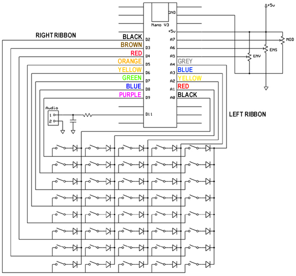
Don’t be frightened by the huge amount of diodes, it’s the keyboard and they are built in.
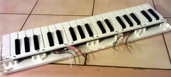
The keyboard used is a Miditech Gargage keys Mini.
It has an 8x5x2 matrix but we only use the 8×5 matrix because the x2 is for measuring velocity and we are not implementing that.
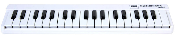
http://www.thomann.de/se/miditech_garagekey_mini.htm
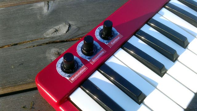
You also need 3 potentiometers used for modulation, ensemble (phaser) and envelope.
The envelope use a preset contour like the Roland JD-Xi where a single knob sets all of the Attack, Decay, Sustain and Release parameters. It selects among commonly used envelopes.
The pots can be of any value as long as they are linear and larger than 5Kohm.
There is a simple filter in the schematics. It’s used for smoothing the PWM signal output by the Nano. You can skip that if you want to be cheap but I recommend that you use it.
Values for the filter components are 1Kohm/100nF.
So I know how to build it, on with the code.
For any code modelled synthesis we start by modelling the oscillators.
In the Solina we have 8 oscillator but we structure them 2 by 2 so that we can use some detune modulation for a thicker sound. So it’s 4 voice polyphonic (or paraphonic).
The code for the oscillators:
//——————– 8 DCO block ——————————————
DCO=0;
for (uint8_t i=0;i<8;i++) {
 if (integrators[i]) integrators[i]–; //Decrement integrators
 DCOPH[i] += FREQ[i]; //Add freq to phaseacc’s
 if (DCOPH[i]&0x800000) { //Check for integrator reset
  DCOPH[i]&=0x7FFFFF; //Trim NCO
  integrators[i]=28; //Reset integrator
 } DCO+=integrators[i];
}
writepointer++;
delayline[writepointer]=DCO;
DCO+=(delayline[(writepointer-lfoval2)&255]*PHASERMIX)>>8;
//——————————————————————– ——-
The first part is the 8 Saw DCO code that create the signal for our 8 oscillators and sum them together.
What is an Integrator?
In the analog World it creates a slope from an impulse.
Great. That is our Saw shape.
Why not use the DCOPH directly as it is saw shaped?
The integrator solution creates a variable sample rate oscillator that doesn’t drop samples so the jitter is largely reduced. There is still some jitter from the phase accumulator but a much better sound.
The second part is a phaser.
A phaser is a delayline of about 50mS where the delaytime is modulated by a LFO.
The output from this delayline is also added to the signal and one of the pots sets the amount of mixed in phaser.
The next part is the envelope and the VCA or volume part of the sound:
//—————— VCA block ————————————
#define M(MX, MX1, MX2) \
asm volatile ( \
“clr r26 \n\t”\
“mulsu %B1, %A2 \n\t”\
“movw %A0, r0 \n\t”\
“mul %A1, %A2 \n\t”\
“add %A0, r1 \n\t”\
“adc %B0, r26 \n\t”\
“clr r1 \n\t”\
: \
“=&r” (MX) \
: \
“a” (MX1), \
“a” (MX2) \
: \
“r26″\
)
if ((ATTACK==255)&&(TRIG==1)) VCA=255;
if (!(envcnt–)) {
 envcnt=20;
 if (VCA<volume) VCA++; if (VCA>volume) VCA–;
}
M(ENV, (int16_t)DCO, VCA);
OCR2A = ENV;
//—————————————————————–
There is some AVR assembler in this and thats because C++ is not fast enough to do 16x8bit signed multiplication for every sample in our waveform in realtime. You don’t need to understand it. It works and is fast.
The last part of our analog modell is the LFO and ENV:
//—————————— LFO Block ———————–
lfocounter+=LFO;
lfoval=(pgm_read_byte_near( sinetable + lfocounter ) * MOD)>>10; //LFO for pitch
lfoval2=pgm_read_byte_near( sinetable + (lfocounter2++) ); //LFO for the Phaser
//—————————————————————–

//——————— ENV block ———————————
if ((TRIG==1)&&(volume<255)) {
 volume+=ATTACK; if (volume>255) volume=255;
}
if ((TRIG==0)&&(volume>0)) {
 volume-=RELEASE;
 if (volume<0) volume=0;
}
//—————————————————————–
The LFO is just a low frequency oscillator that reads the sine table we defined at a slow rate (less than 20Hz) and changes the samplerate with that value.
The ENV sets the conture or envelope (volume in time) of our sound according to the pot and our preset envelope tables.
It changes from long attack/long decay through fast attack/fast decay to fast attack/long decay.
The code also contains a lot of glue to make it work.
One important thing is the keyboard scanner:
//—————— Key scanner —————————–
PORTC|=0x1F;
if ((k&0x38)==(0x00<<3)) PORTC&=B11111110;
if ((k&0x38)==(0x01<<3)) PORTC&=B11111101;
if ((k&0x38)==(0x02<<3)) PORTC&=B11111011;
if ((k&0x38)==(0x03<<3)) PORTC&=B11110111;
if ((k&0x38)==(0x04<<3)) PORTC&=B11101111;
keytable[k]=digitalReadFast((k&7)+2);
if (oldkeytable[k]!=keytable[k]) { //Handle keyevent
 oldkeytable[k]=keytable[k];
 if (keytable[k]==0) {
  handleMIDINOTE(0x90,k+21,127);
  }
  else {
  handleMIDINOTE(0x80,k+21,0);
 }
}
k++;
if (k==40) {
 k=0;
}
digitalWriteFast(10,TRIG);
//—————————————————————
This scans the keyboard, one key at the time by placing a column line low and finding out if a row input is low.
The keyboard gate signal is also output on D10 if you want to use external filters etc and gate an external envelope.
The code is MIDI aware but if you need MIDI input, add this function to the code:
ISR(USART_RX_vect) {
uint8_t MIDIRX;
MIDIRX = UDR0;
/*
Handling “Running status”
1.Buffer is cleared (ie, set to 0) at power up.
2.Buffer stores the status when a Voice Category Status (ie, 0x80 to 0xEF) is received.
3.Buffer is cleared when a System Common Category Status (ie, 0xF0 to 0xF7) is received.
4.Nothing is done to the buffer when a RealTime Category message is received.
5.Any data bytes are ignored when the buffer is 0.
*/
if ((MIDIRX>0xBF)&&(MIDIRX<0xF8)) { MIDIRUNNINGSTATUS=0; MIDISTATE=0; return; } if (MIDIRX>0xF7) return;
if (MIDIRX & 0x80) {
 MIDIRUNNINGSTATUS=MIDIRX;
 MIDISTATE=1;
 return;
}
if (MIDIRX < 0x80) {
 if (!MIDIRUNNINGSTATUS) return;
 if (MIDISTATE==1) {
  MIDINOTE=MIDIRX;
  MIDISTATE++;
  return;
 }
 if (MIDISTATE==2) {
  MIDIVEL=MIDIRX;
  MIDISTATE=1;
  if ((MIDIRUNNINGSTATUS==0x80)||(MIDIRUNNINGSTATUS==0x90)) handleMIDINOTE(MIDIRUNNINGSTATUS,MIDINOTE,MIDIVEL);
  //if (MIDIRUNNINGSTATUS==0xB0) handleMIDICC(MIDINOTE,MIDIVEL);
  return;
 }
}
return;
}
And these global variables:
volatile uint8_t MIDISTATE=0;
volatile uint8_t MIDIRUNNINGSTATUS=0;
volatile uint8_t MIDINOTE;
volatile uint8_t MIDIVEL;
The potentiometers also needs to be scanned:
//————— ADC block ————————————-
while (bit_is_set(ADCSRA, ADSC)); //Wait for ADC EOC
if (MUX==7) DETUNE=((ADCL+(ADCH<<8))>>3);
if (MUX==7) MOD=((ADCL+(ADCH<<8))>>2);
if (MUX==6) PHASERMIX=((ADCL+(ADCH<<8))>>2);
if (MUX==5) ENVELOPE=((ADCL+(ADCH<<8))>>5);
if (MUX==5) ATTACK=ATTrates[ENVELOPE];
if (MUX==5) RELEASE=RELrates[ENVELOPE];
if (RELEASE==255) GATED=0;
if (RELEASE!=255) GATED=1;
if (DETUNE!=olddetune) {
 olddetune=DETUNE;
 for (uint8_t i=0;i<4;i++) {
  if (FREQ[i<<1]) {
   FREQ[(i<<1)|1]=FREQ[i<<1]+(((FREQ[i<<1]/50)>>0)*DETUNE/127);
  }
 }
}
MUX++;
if (MUX>7) MUX=5;
ADMUX = 64 | MUX; //Select MUX
sbi(ADCSRA, ADSC); //start next conversation
//——————————————————————–
They are read one at a time and the analog voltage is interpreted.
Again the low level hardware of the AVR is accessed directly to avoid the overhead of C++ and the Arduino librarys.
Finally our modelled signal is output by using one of the Nano pins used as a DAC at 62.5KHz PWM.
OCR2A = ENV;That’s it.
That’s all that is requred to make a really cool 37-key string synth.
An it uses 3.5mm jacks for the audio and gate outputs so it can be plugged into your modular gear and used as a paraphonic keyboard saw oscillator.
And I hope I inspired you to hack some cool keyboards of your own?
You can download the full source code for upload in an Arduino Nano by clicking the link below and please consider donating an optional amount.
If you don’t want to donate you can just copy and paste the sketch below.
#include <avr/interrupt.h>
#include <avr/io.h>
#include <avr/pgmspace.h>

#ifndef cbi
#define cbi(sfr, bit) (_SFR_BYTE(sfr) &= ~_BV(bit))
#endif
#ifndef sbi
#define sbi(sfr, bit) (_SFR_BYTE(sfr) |= _BV(bit))
#endif


// Standard Arduino Pins
#define digitalPinToPortReg(P) \
(((P) >= 0 && (P) <= 7) ? &PORTD : (((P) >= 8 && (P) <= 13) ? &PORTB : &PORTC))
#define digitalPinToDDRReg(P) \
(((P) >= 0 && (P) <= 7) ? &DDRD : (((P) >= 8 && (P) <= 13) ? &DDRB : &DDRC))
#define digitalPinToPINReg(P) \
(((P) >= 0 && (P) <= 7) ? &PIND : (((P) >= 8 && (P) <= 13) ? &PINB : &PINC))
#define digitalPinToBit(P) \
(((P) >= 0 && (P) <= 7) ? (P) : (((P) >= 8 && (P) <= 13) ? (P) - 8 : (P) - 14))

#define digitalReadFast(P) bitRead(*digitalPinToPINReg(P), digitalPinToBit(P))

#define digitalWriteFast(P, V) bitWrite(*digitalPinToPortReg(P), digitalPinToBit(P), (V))

const unsigned char PS_2 = (1 << ADPS0);;
const unsigned char PS_4 = (1 << ADPS1);
const unsigned char PS_8 = (1 << ADPS1) | (1 << ADPS0);
const unsigned char PS_16 = (1 << ADPS2);
const unsigned char PS_32 = (1 << ADPS2) | (1 << ADPS0);
const unsigned char PS_64 = (1 << ADPS2) | (1 << ADPS1);
const unsigned char PS_128 = (1 << ADPS2) | (1 << ADPS1) | (1 << ADPS0);


uint32_t NOTES[12]={208065>>2,220472>>2,233516>>2,247514>>2,262149>>2,277738>>2,294281>>2,311779>>2,330390>>2,349956>>2,370794>>2,392746>>2};

int8_t keytable[40];
int8_t oldkeytable[40];

const uint8_t ATTrates[32]={
1,2,3,4,5,8,12,20,32,37,43,51,64,85,128,255,0xFF,0xFF,0xFF,0xFF,0xFF,0xFF,0xFF,0xFF,0xFF,0xFF,0xFF,0xFF,0xFF,0xFF,0xFF,0xFF
};

const uint8_t RELrates[32]={
1,2,3,4,5,8,12,20,32,37,43,51,64,85,128,255,255,128,85,64,51,43,37,32,20,12,8,5,4,3,2,1
};


const uint8_t sinetable[256] PROGMEM = {
  127,130,133,136,139,143,146,149,152,155,158,161,164,167,170,173,176,178,181,184,187,190,192,195,198,200,203,205,208,210,212,215,217,219,221,223,225,227,229,231,233,234,236,238,239,240,
  242,243,244,245,247,248,249,249,250,251,252,252,253,253,253,254,254,254,254,254,254,254,253,253,253,252,252,251,250,249,249,248,247,245,244,243,242,240,239,238,236,234,233,231,229,227,225,223,
  221,219,217,215,212,210,208,205,203,200,198,195,192,190,187,184,181,178,176,173,170,167,164,161,158,155,152,149,146,143,139,136,133,130,127,124,121,118,115,111,108,105,102,99,96,93,90,87,84,81,78,
  76,73,70,67,64,62,59,56,54,51,49,46,44,42,39,37,35,33,31,29,27,25,23,21,20,18,16,15,14,12,11,10,9,7,6,5,5,4,3,2,2,1,1,1,0,0,0,0,0,0,0,1,1,1,2,2,3,4,5,5,6,7,9,10,11,12,14,15,16,18,20,21,23,25,27,29,31,
  33,35,37,39,42,44,46,49,51,54,56,59,62,64,67,70,73,76,78,81,84,87,90,93,96,99,102,105,108,111,115,118,121,124

};


volatile uint8_t lfocounter;
volatile uint8_t lfocounter2;
volatile uint16_t lfoval;
volatile uint16_t lfoval2;


volatile uint8_t GATED=1;
uint8_t OSCNOTES[4];
int16_t volume=0;
uint8_t ENVsmoothing;
uint8_t envcnt=10;


//-------- Synth parameters --------------
uint32_t FREQ[16]={0,0,0,0,0,0,0,0,0,0,0,0,0,0,0,0};         //DCO pitch
volatile uint32_t DETUNE=0;       //Osc spread or detune
volatile uint8_t CUTOFF=0;       //freq 0-255
volatile uint8_t RESONANCE=0;      //resonance=0-255
volatile uint16_t LFO=32;           //Lfo rate 0-255
volatile uint8_t VCA=255;          //VCA level 0-255
volatile uint8_t ATTACK=1;           // ENV Attack rate 0-255
volatile uint8_t RELEASE=1;           // ENV Release rate 0-255
volatile uint8_t ENVELOPE=0;          // ENV Shape
volatile uint8_t TRIG=0;           //MIDItrig 1=note ON
volatile int16_t BEND;           //Pitchbend
volatile int16_t MOD;           //MODwheel
//-----------------------------------------

volatile int16_t BENDoffset;           //Pitchbend center
volatile uint32_t olddetune;

uint32_t DCOPH[16];
uint8_t integrators[16];

uint8_t delayline[256];
volatile uint8_t writepointer;
volatile uint8_t PHASERMIX;


uint8_t DCO;
int16_t DCF;
int16_t ENV;

int16_t M0;
int16_t M1;
int16_t M2;
int16_t M3;
int16_t M4;
int16_t M5;
int16_t M6;
int16_t MX1;
int16_t MX2;
int8_t coefficient;

ISR(TIMER1_COMPA_vect) {

 //-------------------- 8 DCO block ------------------------------------------

    DCO=0;
    for (uint8_t i=0;i<8;i++) {
      if (integrators[i]) integrators[i]--;       //Decrement integrators
      DCOPH[i] += FREQ[i];      //Add freq to phaseacc's
      if (DCOPH[i]&0x800000) {                        //Check for integrator reset
         DCOPH[i]&=0x7FFFFF;                           //Trim NCO
         integrators[i]=28;                          //Reset integrator
      }
      DCO+=integrators[i];
    }

    writepointer++;
    delayline[writepointer]=DCO;
    DCO+=(delayline[(writepointer-lfoval2)&255]*PHASERMIX)>>8;

 //---------------------------------------------------------------------------


    //------------------ VCA block ------------------------------------

      #define M(MX, MX1, MX2) \
      asm volatile ( \
        "clr r26 \n\t"\
        "mulsu %B1, %A2 \n\t"\
        "movw %A0, r0 \n\t"\
        "mul %A1, %A2 \n\t"\
        "add %A0, r1 \n\t"\
        "adc %B0, r26 \n\t"\
        "clr r1 \n\t"\
        : \
        "=&r" (MX) \
        : \
        "a" (MX1), \
        "a" (MX2) \
        :\
        "r26"\
      )

    if ((ATTACK==255)&&(TRIG==1)) VCA=255;
    if (!(envcnt--)) {
      envcnt=20;
     if (VCA<volume) VCA++;
     if (VCA>volume) VCA--;
    }
    M(ENV, (int16_t)DCO, VCA);
    OCR2A = ENV;


    //-----------------------------------------------------------------

    //-------------- Calc Sample freq ---------------------------------

    OCR1A = 758-lfoval;

    //-----------------------------------------------------------------
}

ISR(TIMER0_COMPA_vect) {

    //------------------------------ LFO Block -----------------------

    lfocounter+=LFO;
    lfoval=(pgm_read_byte_near( sinetable + lfocounter ) * MOD)>>10;  //LFO for pitch
    lfoval2=pgm_read_byte_near( sinetable + (lfocounter2++) );        //LFO for the Phaser

    //-----------------------------------------------------------------

    //--------------------- ENV block ---------------------------------

    if ((TRIG==1)&&(volume<255)) {
      volume+=ATTACK;
      if (volume>255) volume=255;
    }
    if ((TRIG==0)&&(volume>0)) {
      volume-=RELEASE;
      if (volume<0) volume=0;
    }

    //-----------------------------------------------------------------
}

/*
ISR(USART_RX_vect)
{
	//Midiin.sendByte(UDR0);
}
*/

void setup() {

    //Keyscanner inputs
    pinMode(2,INPUT_PULLUP);
    pinMode(3,INPUT_PULLUP);
    pinMode(4,INPUT_PULLUP);
    pinMode(5,INPUT_PULLUP);
    pinMode(6,INPUT_PULLUP);
    pinMode(7,INPUT_PULLUP);
    pinMode(8,INPUT_PULLUP);
    pinMode(9,INPUT_PULLUP);

    //Keyscanner outputs
    pinMode(14, OUTPUT);
    pinMode(15, OUTPUT);
    pinMode(16, OUTPUT);
    pinMode(17, OUTPUT);
    pinMode(18, OUTPUT);

    //PWM and GATE outputs
    pinMode(11, OUTPUT);
    pinMode(10, OUTPUT);

    // Set up Timer 1 to send a sample every interrupt.

    cli();

    // Set CTC mode
    // Have to set OCR1A *after*, otherwise it gets reset to 0!
    TCCR1B = (TCCR1B & ~_BV(WGM13)) | _BV(WGM12);
    TCCR1A = TCCR1A & ~(_BV(WGM11) | _BV(WGM10));

    // No prescaler
    TCCR1B = (TCCR1B & ~(_BV(CS12) | _BV(CS11))) | _BV(CS10);

    // Set the compare register (OCR1A).
    // OCR1A is a 16-bit register, so we have to do this with
    // interrupts disabled to be safe.
    OCR1A = 758;//F_CPU / SAMPLE_RATE;

    // Enable interrupt when TCNT1 == OCR1A
    TIMSK1 |= _BV(OCIE1A);

    //set timer0 interrupt at 61Hz
    TCCR0A = 0;// set entire TCCR0A register to 0
    TCCR0B = 0;// same for TCCR0B
    TCNT0  = 0;//initialize counter value to 0
    // set compare match register for 62hz increments
    OCR0A = 255;// = 61Hz
    // turn on CTC mode
    TCCR0A |= (1 << WGM01);
    // Set CS01 and CS00 bits for prescaler 1024
    TCCR0B |= (1 << CS02) | (0 << CS01) | (1 << CS00);  //1024 prescaler
    // enable timer compare interrupt
    TIMSK0 |= (1 << OCIE0A);

    sei();
    // Set baud rate to 31,250. Requires modification if clock speed is not 16MHz.
    UBRR0H = ((F_CPU / 16 + 31250 / 2) / 31250 - 1) >> 8;
    UBRR0L = ((F_CPU / 16 + 31250 / 2) / 31250 - 1);
    // Set frame format to 8 data bits, no parity, 1 stop bit
    UCSR0C |= (1<<UCSZ01)|(1<<UCSZ00);

    // enable rx
    UCSR0B |= _BV(RXEN0);

    // USART RX interrupt enable bit on
    UCSR0B |= _BV(RXCIE0);

    // Set up Timer 2 to do pulse width modulation on the speaker
    // pin.

    // Use internal clock (datasheet p.160)
    ASSR &= ~(_BV(EXCLK) | _BV(AS2));

    // Set fast PWM mode  (p.157)
    TCCR2A |= _BV(WGM21) | _BV(WGM20);
    TCCR2B &= ~_BV(WGM22);


        // Do non-inverting PWM on pin OC2A (p.155)
        // On the Arduino this is pin 11.
        TCCR2A = (TCCR2A | _BV(COM2A1)) & ~_BV(COM2A0);
        TCCR2A &= ~(_BV(COM2B1) | _BV(COM2B0));
        // No prescaler (p.158)
        TCCR2B = (TCCR2B & ~(_BV(CS12) | _BV(CS11))) | _BV(CS10);

        // Set initial pulse width to the first sample.
        OCR2A = 128;

        // set up the ADC
        BENDoffset=analogRead(7);
        ADCSRA &= ~PS_128;  // remove bits set by Arduino library

        // you can choose a prescaler from above.
        // PS_16, PS_32, PS_64 or PS_128
        ADCSRA |= PS_128;    // set our own prescaler to 16

        ADMUX = 69;
        sbi(ADCSRA, ADSC);
}

//---------------- Get the base frequency for the MIDI note ---------------
uint32_t MIDI2FREQ(uint8_t note) {
  uint8_t key=note%12;
  if (note<36) return (NOTES[key]>>(1+(35-note)/12));
  if (note>47) return (NOTES[key]<<((note-36)/12));
  return NOTES[key];
}
//-------------------------------------------------------------------------

//---------------- Handle Notes---------------------------------------

void handleMIDINOTE(uint8_t status,uint8_t note,uint8_t vel) {
  uint8_t i;
  uint32_t freq;
  if ((!vel)&&(status==0x90)) status=0x80;
  if (status==0x80) {
        for (i=0;i<4;i++) {
          if (OSCNOTES[i]==note) {
            if (!GATED) {
            FREQ[i<<1]=0;
            FREQ[(i<<1)|1]=0;
            }
            OSCNOTES[i]=0;
          }
        }
        if (!(OSCNOTES[0]|OSCNOTES[1]|OSCNOTES[2]|OSCNOTES[3])) TRIG=0;
        return;
  }

  if (status==0x90) {
    if ((!TRIG)&&(GATED)) {
      for (i=0;i<8;i++) {
        FREQ[i]=0;
      }
    }
    i=0;
    while (i<4) {
        if (!OSCNOTES[i]) {
          freq=MIDI2FREQ(note);
          FREQ[i<<1]=freq;
          FREQ[(i<<1)|1]=FREQ[i<<1]+(((FREQ[i<<1]/50)>>0)*DETUNE/127);
          OSCNOTES[i]=note;
          if (!TRIG) {
            TRIG=1;
          }
          return;
        }
        i++;
    }
  }

}

//-------------------------------------------------------------------------


void loop() {
  //Serial.begin(9600);
  uint8_t k=0;
  uint8_t z;
  uint8_t w=0;
  int8_t MUX=5;
  while(1) {
    //------------------ Key scanner -----------------------------
      PORTC|=0x1F;
      if ((k&0x38)==(0x00<<3)) PORTC&=B11111110;
      if ((k&0x38)==(0x01<<3)) PORTC&=B11111101;
      if ((k&0x38)==(0x02<<3)) PORTC&=B11111011;
      if ((k&0x38)==(0x03<<3)) PORTC&=B11110111;
      if ((k&0x38)==(0x04<<3)) PORTC&=B11101111;
      keytable[k]=digitalReadFast((k&7)+2);
      if (oldkeytable[k]!=keytable[k]) { //Handle keyevent
        oldkeytable[k]=keytable[k];
        if (keytable[k]==0) {
          handleMIDINOTE(0x90,k+21,127);
        }
        else {
          handleMIDINOTE(0x80,k+21,0);
        }
      }
      k++;
      if (k==40) {
        k=0;
      }
      digitalWriteFast(10,TRIG);
  //---------------------------------------------------------------

  //--------------- ADC block -------------------------------------

  while (bit_is_set(ADCSRA, ADSC)); //Wait for ADC EOC

      if (MUX==7) DETUNE=((ADCL+(ADCH<<8))>>3);
      if (MUX==7) MOD=((ADCL+(ADCH<<8))>>2);

      if (MUX==6) PHASERMIX=((ADCL+(ADCH<<8))>>2);
      if (MUX==5) ENVELOPE=((ADCL+(ADCH<<8))>>5);
      if (MUX==5) ATTACK=ATTrates[ENVELOPE];
      if (MUX==5) RELEASE=RELrates[ENVELOPE];

      if (RELEASE==255) GATED=0;
      if (RELEASE!=255) GATED=1;
      if (DETUNE!=olddetune) {
        olddetune=DETUNE;
        for (uint8_t i=0;i<4;i++) {
          if (FREQ[i<<1]) {
          FREQ[(i<<1)|1]=FREQ[i<<1]+(((FREQ[i<<1]/50)>>0)*DETUNE/127);
        }
      }
      }
      //Serial.print(CUTOFF,DEC);
      //Serial.print("\n");

      MUX++;
      if (MUX>7) MUX=5;
      ADMUX = 64 | MUX; //Select MUX
      sbi(ADCSRA, ADSC); //start next conversation

   //--------------------------------------------------------------------

  }
}